Machinery and equipment used in factories and other facilities are equipped with an emergency stop function to stop the machinery and equipment in an emergency for ensuring operator safety as an complementary protective measures (Figure 1).
The emergency stop switch is installed as the input device for this function. This switch is manually operated by the operator when the operator senses danger, an abnormality in the machinery, equipment, or workpiece, or the possibility of damage (Figure 2).
Constructional requirements of Emergency Stop Switch
Button Color and Shape
The operation panel of a piece of machinery and equipment has many operation pushbuttons and indicators.
Among them, emergency stop switches must be easily recognizable and operable in case of emergency. For this reason, the button is red and shaped to be easily pressable with the palm of the hand. Also, the background color of the switch is yellow. This conspicuous color combination of a red button on a yellow background helps the operator recognize the emergency stop switch in case of emergency (Figure 3).
NC (Normally Closed) Contact
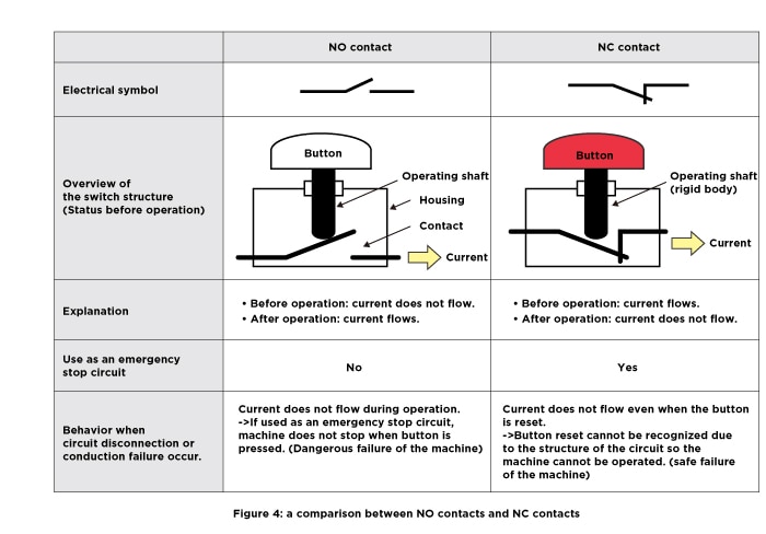
There are two types of switch contacts: normally open (NO) and normally closed (NC) (Figure 4).
International safety standards and other countries' safety standards require that NC contacts must be used in emergency stop switches. The reasons for this are explained below:
Suppose we mistakenly use an NO contact for the emergency stop switch, as shown in the figure on the left in Figure 4.
Then, when the button is not pressed (not in an emergency state), the NO contact is open and no current flows through the circuit, but when the button is pressed, the NO contact closes and a current that signals the emergency state flows through the circuit, bringing the machinery and equipment to an emergency stop. However, if there is an abnormality in the circuit, such as a foreign object attached to the NO contact or wiring disconnection, no current will flow through the circuit, resulting in a dangerous failure where an emergency stop cannot be applied to the machine even if the button is pressed.
On the other hand, for an emergency stop switch using an NC contact shown in the figure on the right side of Figure 4, the contact is closed when the button is not pressed. When the button is not pressed (not in an emergency state), the NC contact is closed, and so current flows through the circuit. Then, when the button is pressed, the NC contact is opened to interrupt the current and bring the machinery and equipment to an emergency stop. In other words, the emergency stop signal from the emergency stop switch functions as an emergency stop output by interrupting the current that had been flowing (meaning that it is in a safe state).
In this case, if there is an abnormality in the circuit, such as a foreign object attached to the NC contact or wiring disconnection, the current will not flow in the circuit, resulting in a safe failure that prevents the machinery and equipment from operating.
In this way, the NO contact and NC contact have different failure states when there is an abnormality in the circuit.
From a safety point of view, which failure state is preferable?
Components used in safety-related control systems, such as emergency stop switches, are required to perform a safe failure, which is a failure on the side that stops the machine in the event of its own failure. For this reason, the standards require the use of NC contacts for emergency stop switches.
Direct Opening Action
The direct opening action is a function that ensures that the force of pressing the button is reliably transmitted as the force to open the NC contact.
Even if the contact is welded (A state where the contact surface melts and then cools and adheres due to an inrush current exceeding the capacity during contact opening and closing) shut, the NC contact can be opened reliably by pushing the button.
For this reason, everything from the operation buttons to the contacts must be made of rigid and solid parts, as shown in the right figure in Figure 4.
It is not possible to transmit the force that presses the button using resilient components such as springs along the transmission path. This is because if an resilient component such as a spring is damaged, the NC contact cannot be opened by pressing the button.
Latching Mechanism (Self-holding Mechanism)
In general, emergency stop switches are activated in case of emergency, and so when the button is pressed, the NC contact opens to interrupt the current, and at the same time, a latching mechanism is activated to hold the button in the pressed-down position. This allows the current interruption state to be maintained, thus preventing unintended restarting of machinery and equipment.
After confirming safety, there are two ways to release the latch and return the button to its original position: by turning the button in a specified direction (turn-reset type) or by pulling the button back to its original position (pull-reset type). The prevailing reset type varies by the region. For this reason, there are dual-purpose types that can be reset by both turn and pull reset for enabling use in any region (Figure 5).
Product Descriptions of X Series Emergency Stop Switches
Required Installation Location
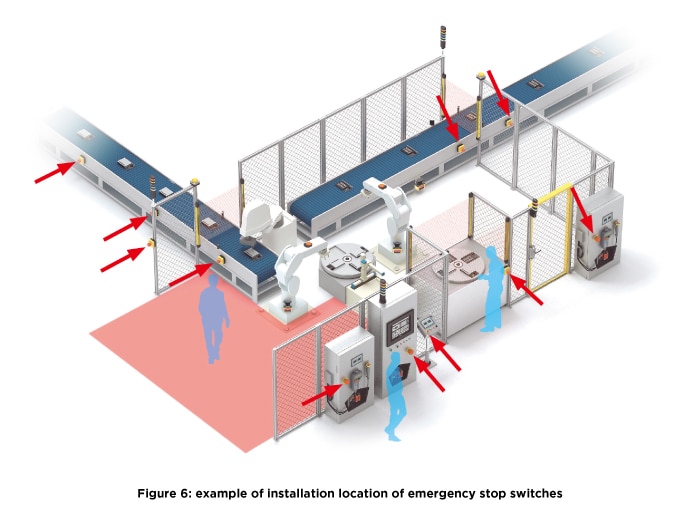
The standards require that emergency stop switches be installed in the following locations in machinery and equipment.
● Locations required as a result of risk assessment
● On each operation panel (except when not required as a result of risk assessment)
● At the entrance and exit of machinery and equipment
● Locations where operator intervention is needed to operate the machine, such as hold-to-run control functions and enable control functions
● All locations where intervention between the operator and the machine is expected, such as workpiece loading/unloading ports


