Your browser does not support JavaScript!
Skip to content Skip to navigation menu

ISO12100 | USA

ISO/IEC Guide 51, a guideline for the establishment of safety standards that was jointly developed by ISO and IEC, requires that a systemic approach be adopted to establish safety standards. In terms of the system of standards, standards are divided into ① basic safety standards, ② group safety standards, and ③ machine safety standards. This document explains ISO12100, which is a basic safety standard.


Basic safety standards, also known as “Type-A standards,” primarily specify the principles and methodologies of risk assessment and risk reduction, which are important to achieve safety in the design of machinery . 


Risk assessment refers to organizational activities at the workplace, which are carried out to identify risk  that exists or potentially exists at the workplace and to eliminate or adequately reduce such risk before they cause an industrial accident.

As advances in technology and expansion into new markets increasingly diversify machines and working environments, causes of industrial accidents are also becoming increasingly complicated and diversified. Under these circumstances, there is potential risk at the workplace, and leaving it without taking any measures can invite the occurrence of industrial accidents.
Therefore, it is important to proactively identify potential risk that may exist at the workplace and take appropriate measures before occupational hazards occur. In order to do this, “risk assessment and risk reduction” are required.
 

Definitions of important terms that are used in carrying out risk assessment (Note)


●Harm
 Physical injury or damage to health.

●Hazard
 Potential source of harm.

●Hazardous event
 Event that can cause harm.

●Hazardous situation
 Circumstance in which a person is exposed to at least one hazard.

●Risk
  Combination of the probability of occurrence of harm and the severity of that harm.

●Safety
  Freedom from risk which is not tolerable. This is achieved by reducing the risk to a tolerable level.

●tolerable risk
  Freedom from risk which is not tolerable. This is achieved by reducing the risk to a tolerable level.


Note) Quoted and adapted from ISO12100 and ISO/IEC Guide 51
 

1-1. Outline of the risk assessment procedure

Determination of the limits of the machinery
Start with determining the limits of the relevant machine. Identify the overall specifications of the machine and specify the scope and conditions of risk assessment. 
 To do these, it is important to specify the following three matters: 
●Limits and conditions of use;
●Limits and conditions of space; and 
●Limits and conditions of time.

Hazard identification
Identify reasonably foreseeable hazards, hazardous situations and/or hazardous events throughout the machine life cycle (i.e: transport, assembly, use, scrapping).

Risk estimation
For all the hazards identified in Procedure 2, individually estimate the risk.

Risk evaluation
Evaluate and validate the result of risk estimation and the risk reduction.

1-2. Outline of the risk reduction procedure

What is risk reduction?

Risk reduction refers to reducing both of “severity of harm” and “probability of occurrence of harm,” or either one of them. Risk reduction shall be achieved by the following 3-step method described below.


Three-step method

Step 1: Inherently safe design measures
These refer to reducing the risk inherent in the machine by eliminating a hazard itself through the review of the design and operation work of the machine, or by reducing “severity of harm” or “probability of occurrence of harm.” This step is important because it is the only one to which a hazard can be eliminated.


- Reduce driving energy, lower the circuit voltage, use harmless substances.
- Reduce to the minimum the number of opportunities for exposure to hazards by automating the feeding / extraction of materials into / from processing machinery., etc. 
Step 2: Safeguarding and complimentary protective measures
1) Safeguarding
When it was not possible to adequately reduce the risk through inherently safe design measures, use a guard or a protective device to protect people. Because hazards themselves persist, the concept of “safeguarding through isolation” or “safeguarding through a stop” is primarily used.
 

- Put a guard to prevent people from touching a hazard, seal the machine to prevent substances from being released.
- Put an interlock system  that stops a hazard when the guard is opened.
2) Complimentary protective measures
In addition to safeguarding, complimentary protective measures are also important measures to ensure safety. Examples include installing an emergency stop device, providing the machine with measures to reliably shut down the power source and make the residual energy zero.
 
Step 3: Information for use
When there is still a risk for which adequate reduction was not possible through inherently safe design measures as well as safeguarding and complimentary protective measures, that shall be clearly communicated to users through “Information for use.”

 
- Operating procedures for use of the machinery
- Required training
- Personal protective equipment (e.g., protective glasses )
- Precautions, warning marks, etc. regarding residual risks.
 
Important: It is not permitted to provide only information for use (e.g., warning marks, training) without implementing inherently safe design measures, safeguarding, or complimentary protective measures.
This section explains risk assessment procedures according to the flow from Procedure 1 to 4 shown in Figure 2.

2-1. Procedure 1 Determination of the limits of the machinery

Machines are required to be safe, easy to use, and productive. A risk assessment is carried out by taking into account these conditions and determining the range of restrictions applied in actual use. As mentioned earlier, restrictions on use, restrictions on space, and restrictions on time are clarified.

1. Use limits 

●The different machine operating modes and different intervention procedures for the users.
●Use of machinery  identified by sex gender, ages, or physical ability.
●Training, experience, or ability of users
These need to take into account the intended use and the reasonably foreseeable misuse.
 
- Intended use
Use of a machine in accordance with the information for use provided in the instructions.
- Reasonably foreseeable misuse
Use of a machine in a way not intended by the designer, but which can result from readily predictable human behavior.

2. Space limits  

● Movable range of a machine (e.g., arm part of a robot, moving range of a crane).
● Proper work area for those who work with a machine during normal operation or maintenance.
● Proper “Operator”-“Machine” positional relationship and interface
● “Machine”-“Power (e.g., electric power)” interface
 

3. Time limits 

●The life limit of the machinery and/or of some of its components. 
Examples include an edge of cutting tools, air/oil filter, grease, lubricant, gasket, and make and break contact of switches.
● Recommended service intervals .
 

2-2. Procedure 2 Hazard identification

Hazard identification constitutes a very important step in risk assessment.
If a hazard is overlooked, a machine at high risk can be actuated without taking the necessary safety measures, which may result in a serious accident.


Hazard, hazardous situation, and hazardous event

Described below is a list of hazards shown in ISO12100 (extracted from ISO12100 Annex B, Table B.1).

This list does not cover all the hazards. Neither does it provide the order of priority. However, it will serve as a very helpful material when a person performing a risk assessment exhaustively identifies hazards.
Table 1 List of typical hazard types
No.Type of hazardExamples of hazard    
OriginPotential consequences
1

Mechanical hazards

- Acceleration, deceleration
- Angular parts
- Approach of a moving element to a fixed part;
- Cutting parts
- Elastic elements
- Falling objects
- Gravity
- Height from the ground
- High pressure
- Instability
- Kinetic energy
- Machinery mobility
- Moving elements
- Rotating elements
- Rough, slippery surface
- Sharp edges
- Stored energy
- Vacuum

- Being run over
- Being thrown
- Crushing;
- Cutting or severing
- Drawing-in or trapping 
- Entanglement
- Friction or abrasion
- Impact
- Injection
- Shearing
- Slipping, tripping and falling
- Stabbing or puncture
- Suffocation


2

Electrical hazards


- Arc
- Electromagnetic phenomena
- Electrostatic phenomena
- Live parts
- not enough distance to live parts under high voltage
- Overload
- Parts which have become live under fault conditions
- Short-circuit
- Thermal radiation
- Burn
- Chemical effects
- Effects on medical implants
- Electrocution
- Falling, being thrown
- Fire
- Projection of molten particles
- Shock
3

Thermal hazards

- Explosion
- Flame
- Objects or materials with a high or low temperature
- Radiation from heat sources

- Burn
- Dehydration
- Discomfort
- Frostbite
- Injuries by the radiation of heat sources
- Scald
4

Noise hazards


- Cavitation phenomena
- Exhausting system
- Gas leaking at high speed
- Manufacturing process (stamping, cutting, etc.)
- Moving parts
- Scraping surfaces
- Unbalanced rotating parts
- Whistling pneumatics 
- Worn parts

- Discomfort
- Loss of awareness
- Loss of balance
- Permanent hearing loss
- Stress
- Tinnitus
- Tiredness
"- Any other
(for example, mechanical, electrical) as a consequence of an interference with speech communication or with acoustic signals"

5

Vibration hazards


- Cavitation phenomena
- Misalignment of moving parts
- Mobile equipment
- Scraping surfaces
- Unbalanced rotating parts
- Vibrating equipment
- Worn parts

- Discomfort
- Low-back morbidity
- Neurological disorder
- Osteo-articular disorder
- Trauma of the spine
- Vascular disorder

6

Radiation hazards


- Ionizing radiation source
- Low-frequency electromagnetic radiation
- Optical radiation (infrared, visible and ultraviolet rays), including lasers
- Radio-frequency electromagnetic radiation

- Burn
- Damage to eyes and skin
- Effects on reproductive capability
- Mutation
- Headache, insomnia, etc.
7

Material / substance hazards

'- Aerosol
- Biological and microbiological (viral or bacterial) agents
- Combustible
- Dust
- Explosive
- Fiber
- Flammable
- Fluid
- Fume
- Gas
- Mist
- Oxidizer

- Breathing difficulties, suffocation
- Cancer
- Corrosion
- Effects on reproductive capability
- Explosion
- Fire
- Infection
- Mutation
- Poisoning
- Sensitization


8

Ergonomic hazards

- Access
- Design or location of indicators and visual displays units
- Design, location or identification of control devices
- Effort 
- Flicker, dazzling, shadow, stroboscopic effect
- Local lighting
- Mental overload/underload
- Posture
- Repetitive activity
- Visibility

- Discomfort
- Fatigue
- Musculoskeletal disorder
- Stress
"- Any other
 (for example, mechanical, electrical) as a consequence of a human error"

9Hazards associated with environment in which the machine is used- Dust and fog
- Electromagnetic disturbance
- lightning 
- Moisture
- Pollution
- Snow 
- Temperature 
- Water 
- Wind 
- lack of oxygen

- Burn
- Slight disease
- Slipping, falling
- Suffocation
- Any other as a consequence of the effect caused by the sources of the hazards on the machine or parts of the machine

10Combination of hazards- For example, repetitive activity + effort + high environmental temperature- For example, repetitive activity + effort + high environmental temperature

Hazards are classified into different groups by type such as the mechanical, noise, or vibration hazard as shown in the list, and it is recommended that hazards be expressed as a combination of “cause” and “effect” according to the type of hazard. For example, they are expressed as follows:
- ”Cutting” due to “Angular parts”
- ”Stabbing” due to “Sharp edges”
- ”Impact” due to “Kinetic energy”
- ”Electrical shock” due to“Live parts”  
- ”Burn” due to contact with “materials with a high temperature”

For information such as the lists of hazardous situations and hazardous events, please see ISO12100 Annexes B.2 to B.4


Matters that require attention in identifying hazards

 Described below are matters that require attention in identifying hazards.

● Serious hazards
Although it is desirable to extract all hazards, large and small, efforts shall be made to ensure that serious hazards in particular will never be overlooked.

● Definitive (permanent) hazards
These are hazards that exist permanently during the use of a machine, including the moving part and the energized part of a machine, high / low temperature, unhealthy posture, noise, and (X ray) radiation. These are relatively easy to be identified as hazards, but if overlooked, people will constantly be exposed to hazards.

● Accidental hazards
These include getting caught as a consequence of an unexpected start / restart, a fall as a consequence of acceleration / deceleration, fire, and explosion. These hazards require particular attention as they occur unexpectedly and are difficult to identify.
● Hazards of damage to health
Generally, it is considered difficult to compare an approach to damage to health with an approach to damage (injury) on the same table. In considering harm that can accumulate, including damage to health, it is necessary to determine “severity of harm” by taking into account the frequency and time of exposure.
 

Methods of hazard identification

ISO12100 introduces the lists of hazards and hazardous events but does not provide specific methods for identifying hazards in practice. Therefore, described below are helpful methods that can be used to avoid overlooking hazards.

● Hazard listing method
This is a method in which all the hazards are extracted in each manufacturing process in, for example, a long production line that covers charging of materials to carrying out of finished products.
In this case, it is necessary to identify not only hazards during routine work but also hazards during non-routine work like a set-up change and maintenance. Attention should also be paid to hazards at the time of reasonably foreseeable misuse, including correcting abnormality without stopping the process.

● Method that uses work analysis
This is a method in which hazards are identified on the basis of the workers’ workflow. For existing lines, there are work instructions for workers. In this method, these instructions are used to perform work as well as to identify hazards. However, since work instructions are still not in place at the design stage of a machine, for example, this method is considered effective for existing production lines.
It is also important not to exclude hazards that exist just because there is no work at those particular places.

● Utility tracing method
In cases where major hazards are utilities (energy) such as electric power, compressed air, steam, or fluidic injection, this method focuses on the sections that use such energy and extracts them as hazards. It traces the consumers of utilities, and any mechanical movement or fluidic injection detected are examined as to whether they can become hazards.
It should be noted that this method requires the consideration of hazards, including a sharp protrusion, an ergonomic hazard (working in an unhealthy posture), or potential energy (putting a heavy object in the upper part of a shelf), in addition to utilities.

Whichever method is used, extracting hazards while referring to the list provided in ISO12100 Annex B will help exhaustively identify hazards.

Other matters to be considered in identifying hazards

● The same hazard with different patterns of work has different hazardous events/hazardous situations. For example, in the case of the routine work in which materials are manually charged between the upper and lower molds, with items being carried out after processing, the part that is most likely to suffer is the upper arm. As a protective measure for this, an item like a light curtain is generally used.
Meanwhile, for the non-routine work in which the body is put between the upper and lower molds to clean them during maintenance, the part that is most likely to suffer is the upper part of the body, and if it suffers, that could be a fatal wound. Preventive measures for this include providing the molds with a fall-preventing mechanism as well as fixing the upper and lower molds with sleepers. Therefore, the same hazard may have multiple hazardous events, and if it does, multiple protective measures are required accordingly.
 
● It is also important to check whether or not protective measures that have already been adopted constitute a new hazard. Examples include checking that the edge of a guard that was put will not cause injury or checking that people will not be caught between a guard that was put around a robot, for example, and the robot arm.
 

2-3. Procedure 3 Risk estimation

After hazards are identified, a risk estimation is made for hazardous situations resulting from each hazard.

Risk and its elements

A risk (R) is expressed as a combination of “Severity of harm (S)” and “Probability of occurrence of that harm (P)” in a case where harm is caused by a hazard of the relevant machine. “Probability of occurrence of that harm (P)” consists of the following elements: “Probability of occurrence of the hazardous event (P1), “Frequency of exposure (F),” “Time of exposure (T),” and “Possibility to avoid the harm (Q).”

Explanation of each element 

To specifically estimate a risk, criteria such as “Severity of harm (S)” and “Probability of occurrence of that harm (P)” are required.
This enables a risk to be estimated with the same criteria for every machinery and makes comparisons possible.
However, ISO12100 does not specify such criteria.


Risk estimation

Several methods are available to estimate a risk. Since ISO12100 does not provide a specific method, described below are methods from the guidelines for risk assessment, published by the Ministry of Health, Labour and Welfare of Japan, and ISO/TR14121-2.
 

1. Summation method / multiplication method

This is a method in which all the elements necessary to estimate a risk are given a certain score and those scores are summed or multiplied.
In the example below, “Severity of harm (S)” is divided into four ranks, and “Probability of occurrence of that harm (P)” is expressed as a combination of “Probability of occurrence of the hazardous event (P1)” and “Frequency of exposure (F).” These elements are summed or multiplied.
This method is characterized by the inclusion of all the necessary elements in the calculation.

2. Risk matrix method

Generally, in this method, “Severity of harm (S)” is plotted on vertical axis and “Probability of occurrence of that harm (P)” on the horizontal axis, with each section being assigned a risk index value. This method is characterized by its ability to visualize a risk to make it easy to understand.

3. Risk graph method

This method basically uses the three types of elements: “Severity of harm (S),” “Frequency of exposure (F),” and “Possibility to avoid the harm (P).” It is based on the system of a choice between the two and thought to cause relatively small variations.

4. Risk graph used for safety-related parts of control systems

Figure 6 is the risk graph used in ISO13849-1: 2015. It is used to carry out a risk assessment for safety-related parts of control systems and to determine the required performance level (PLr).

5. Hybrid method (based on IEC62061 Annex A, or ISO/TR14121-2)

This method is considered to be a combination of the summation method and the risk graph method. It is also used to estimate the safety integrity level (SIL) of safety-related parts of control systems in IEC62061.

Described below are mostly from IEC62061.


(1) Severity of harm (Se) at the relevant hazard

Supplement to the severity of harm
4 is a fatal or a significant irreversible injury such that it will be impossible or at least very difficult to continue the same work after healing, e.g. loss of limbs, pulmonary permanent damages, loss of an eye or partial or total loss of the sight . 
3 is a major or irreversible injury in such a way that it can be possible to continue the same work after healing such as loss of some fingers or toes. It can also include a severe major but reversible injury such as broken limbs.
2 is a more severe reversible injury which requires attention from a medical practitioner and it is possible to resume the work activity after a short period of time, e.g. severe lacerations, stabbing, and severe bruises .
1 is a slight injury where first aid cares without medical intervention are sufficient, e.g. minor injury including scratches and minor bruises.
 
(2) Probability of occurrence of that harm
Each of the three elements, namely, “Frequency and duration of exposure ,” “Probability of occurrence of the hazardous event,” and “Probability of avoiding or limiting harm, ” is determined and added up to determine the class of expected harm (CL).

1.Exposure level (Fr)

Supplement to the level of exposure

5: An exposure frequency of once every hour or more
5 (*): Approximately once every hour to every day
4 (*): Approximately once every day to every two weeks
3 (*): Approximately once every two weeks to every year
2 (*): An exposure frequency of once every year or less

* The exposure level may be lowered by one level if the duration of exposure is 10 minutes or less.

2. Probability of occurrence of dangerous event (Pr)

Supplement to the probability of occurrence

5: Very high. Not designed for that particular use from the beginning. Or the probability of a failure that can cause a hazardous event is high. The probability of human error is high.
4: Likely. Failures that can cause hazardous events occur. Human errors occur.
3: Possible. Failures that could cause hazardous events can occur. Human errors can occur.
2: Rarely. Failures that could cause hazardous events are unlikely. Human errors are unlikely.
1: Negligible. Failures that could cause hazardous events are very unlikely. There is no probability of human error.

3. Probability of avoiding harm (Av)

Supplement to the avoidance of harm

5: Impossible. It is impossible to avoid the sudden appearance of strong laser beams, or explosion, for example.
3: Rarely. For example, if the speed of a moving part is sufficiently slow and there is enough space, it is possible to avoid an approaching hazard.
1: Probable. When operation continues even after an interlock fails, if a certain safety distance is secured, it is possible to avoid contact with the moving part behind the interlock guard.

(3) SIL assignmen

SIL is assigned using the table below.
The point of intersection of CL (the total value of “Frequency and duration of exposure (Fr),” “Probability of occurrence of the hazardous event (Pr),” and “Probability of avoiding or limiting harm (Av)”) on the horizontal axis with “Severity of harm (Se)” on the vertical axis is determined to be the SIL of the required control system.

2-4. Procedure 4 Risk evaluation

After a risk estimation is completed, a risk evaluation is made to determine whether risk reduction is necessary.
If the result shows that the risk is not at a “tolerable level” or lower, a risk reduction measure (the 3-step method) is applied and implemented.
When a new protective measure is applied for risk reduction, confirmation is required as to whether that new measure has not caused a new hazard or increased other risks. If a new hazard is caused, or other risks are increased, the procedure for risk estimation needs to be initiated anew.
 

Concept of a tolerable risk level

Although a tolerable risk level is not specified in the international safety standards including ISO12100, it is important to define a tolerable risk level before carrying out a risk assessment as an organization. If a tolerable risk level is changed in the middle of risk assessment activities, that can affect protective measures that have been implemented up to that time.
   

3-1. Typical examples of inherently safe design measures

Consideration of geometrical factors and physical aspects

1. Geometrical factors

Arrange a machine/equipment so that an operator can directly see a hazard zone from the position where he/she controls the machine/equipment. An item like a mirror shall be attached to an invisible section to ensure that safety can be confirmed.

2. Securing a safety gap between devices

Make a gap wide enough so that an operator can enter safely without being caught even if there is a moving part, or completely fill a gap so that the body (or a part of the body) will not enter.

3. Avoiding sharp edges and corners

Do not create sharp edges or pointed parts. Put covers on such parts, if any.
Make surfaces smooth to prevent clothes to be caught.


4. Physical aspects

- Limiting the actuating force to a sufficiently low value so that the actuated part does not generate a mechanical hazard.
- Limiting the emissions. That is, take measures to address the origin by, for example, reducing noise at the source of the sound or reducing vibration at the source of the vibration.
- Replace hazardous substances with safe ones. Or change a process to one that generates less hazardous substances.


5. Taking into account general technical knowledge of machine design

- Perform proper stress calculations. Take into account dynamic balancing as well.
- Select appropriate materials and grades. Select materials by taking into account factors such as corrosion, abrasion, and inflammability.


6. Choice of appropriate technolog

For a machine that is used in an atmosphere with a possibility of an explosion hazard, use a hydraulic/pneumatic control system in place of an electric circuit, or use electric equipment with an intrinsically safe structure.
If a pneumatic device generates a lot of noise, use an electrical system instead.


7. Applying principle of positive mechanical action

An operating principle that achieves operation by constructing a machine component using only rigidity elements. Therefore, do not use a spring or an elastic body in the middle of a transmission path.
Examples of application include a direct opening mechanism through NC contacts in an emergency stop switch and an interlock switch (door interlock device).

Stability, maintainability, etc.

1. Provisions for stability
Machines are required to be designed/installed to have a sufficient stability with respect to the installation position.

2. Provisions for maintainability
To facilitate maintenance work, ensure easy access to the relevant part.
Ensure easy handling, and the work should be completed without using tools to the extent possible.


Measures to prevent electrical hazards

ISO12100 stipulates that IEC60204-1 should be referred to regarding the safety of the electrical equipment of machines.
IEC60204-1 (Safety of machinery – Electrical equipment of machines – Part 1: General requirements) provides requirements for protection from the disconnection and opening and closing of electric/control circuits as well as an electric shock/fire in order to protect people and electrical equipment mainly from electrical hazards.
 

Protection from hydraulic and pneumatic hazards

Hydraulic and pneumatic devices and systems are required to be designed by considering the following matters:
- To maintain pressure within a specified limit using a pressure-limiting device, for example;
- To prevent a pipe or hose from making a sudden movement as if it were bowed like a whip as a result of oil or air leakage; and
- To design containers of compressed gas, etc. so that they will automatically reduce pressure to the extent possible when the energy source of a machine is interrupted.
- Even in cases where pressure cannot be reduced, means of pressure interruption and local pressure reduction as well as a pressure display shall be provided.
 

Observing ergonomic principles

In order to reduce operator’ physical/mental stress, the following consideration is required in design:
● To ensure that the operation of a machine will be carried out at the position/height that does not force an operator to take an unhealthy posture;
● To ensure that the position of operation will be free from the influences of noise/vibration or (high/low) temperature;
● To ensure that an operator will not be forced to change his/her working pace to keep pace with the cycle of automatic operation;
● To provide proper lighting for the working space (it shall not be too bright); and
● Selection/arrangement and identification of actuators such as switches and levers.
 
- Switches, etc. to be operated shall be clearly recognizable.
- The arrangement of switches, indicators, etc. shall be standardized so that the possibility of an operational error will be reduced even after the operator moves to another machine.
- The direction of a movement of a switch / lever shall coincide with the expected effect of that operation (See Figure 11).

Applying inherently safe design measures to control systems

1. Avoidance of a hazardous situation from the starting of an internal power source/switching on an external power supply
Machines such as mobile machines shall not operate only because the engine started. In addition, machines shall not start the actuating part only because they are connected to the source of main power supply.
2. Starting/stopping of a mechanism
- It is recommended that mechanism should be started by the impression (or the increase) of voltage or fluid pressure. This corresponds to a transfer from 0 to 1 in the expression using the binary logic (with 1 indicating the state of energy H: High)
- It is recommended that mechanism should be stopped by the removal (or the reduction) of voltage or fluid pressure. This corresponds to a transfer from 1 to 0 in the expression using the binary logic (with 0 indicating the state of energy L: Low)
 
3. Prevention of a restart after power interruption
If a hazard could be generated, the spontaneous restart of a machine when it is re-energized after power interruption shall be prevented Examples include constructing a self-hold circuit using a relay.
4. Interruption of power supply
Machinery shall be designed/manufactured so that they will not cause a hazardous situation because of, for example, the interruption of power supply.
The stop function shall be maintained. And objects such as a work piece (heavy object) held by machinery shall be maintained during the time that is required to safely move it to a lower position.
 
5. Safety functions implemented by programmable electronic control systems
Concerning control systems including a PLC (programmable logic controller), those that have a sufficiently low probability of random hardware failure as well as a low probability of systematic failure in safety-related parts of the control system shall be designed.
In addition, validation is required to ensure that the specified performance [for example, safety integrity level (SIL) in IEC 61508] for each safety function has been achieved.
It is recommended that application software should not be changed by users at their discretion. In cases where program changes by users are necessary, limiting access to software related to safety-related functions is recommended (e.g., use of a lock or password).
 
6. Principles relating to manual control 
- Manual control devices shall be designed and located according to the relevant ergonomic principles.
- The stop switch shall be placed near each start control device..
- Switches shall be placed at a location that cannot be reached from a hazard zone and need to be operational only at a safe place (excluding, however, those that are unavoidably placed within a hazard zone, such as an emergency stop switch or a teach pendant).
- The placement of a controller and the position to operate shall be located so that the operator is able to confirm a hazard zone.
- In cases where one machine (or hazard) can be started by multiple controllers, a control circuit shall be designed to allow only one controller to be effective.
This requirement applies particularly, for example, to a teach pendant that an operator brings into a hazard zone.
- Switches shall be designed to become operational only when they are intentionally operated or to provide a guard to prevent malfunction in areas at risk.
- For the safety of directly control by the operator, measures shall be implemented to ensure that an operator will be at a safe control position. Examples include the use of a two-hand control device.
- For cableless control, a machine shall be stopped during communication interruption or when correct control signals are not received (see IEC60204-1).
 
7. Control modes for each work (e.g., setting, teaching, process changeover, fault-finding, cleaning or maintenance)
When a machine or a part of a machine is operated in a state in which the guard is removed and/or in a state in which the safeguard device is made ineffective unavoidably to conduct work, safety shall be ensured by the following requirements:
- To disable all other control modes;
- To permit operation in that particular mode only by the operation of an enabling device, two-hand control device, or hold-to-run control device; and
- To permit operation in that particular mode only in a state in which risks are reduced, including at low speed, with restricted force or motion.
 
Note that this control mode shal be associated with one or more of the following measures:
(1) To take measures to restrict access to a hazard zone to the extent possible;
(2) To place an emergency stop switch within the reach of an operator; and
(3) To use a teach pendant and/ or a local controller that is placed at allowing sight of the controlled elements.

 
8. Proper selection of control and operating modes
In machinery that uses multiple operation modes, different modes have different risk levels and protective measures, and thus, it shall be fitted with a mode selector which can be locked in each position. For example, the position of a mode switching device like a selector switch with a key shall be clearly identifiable.

Measures to minimize the probability of failure of safety functions

The safety of machinery requires not only the reliability of control systems but also the reliability of all parts of a machine. To achieve this, the requirements below need to be met.
1. Use of reliable components
Use components that have a low failure rate under the conditions (i.e., period, number of times) specified in the specifications and can withstand all kinds of disturbances and stresses.
2. Use of “oriented failure mode” components
Use components (systems) with an “oriented failure mode” for which a failure mode is known beforehand.
A typical example of components with an oriented failure mode is a fuse used for overcurrent protection. A fuse has a failure mode, by which it does not short-circuit but fuses to interrupt current when overcurrent flows.
3. Duplication (or redundancy) of components or subsystems
Concerning safety-related parts of control systems, making components (and signal paths) duplexed will maintain safety functions even if one component fails because the other component can properly operate to, for example, safely stop the machine. Moreover, giving diversity to designs and/or technologies, in addition to making components or subsystems duplexed, will be effective for common cause failure (CCF) and common mode failure.
4. Use of automatic monitoring 
In safety-related parts of control systems, an automatic monitoring function is used to detect a single failure without interfering with safety functions (e.g., stop a machine by pressing an emergency stop switch). If a single failure is found by monitoring, protective measures are taken, including safely stopping the machine. After a machine is stooped, steps may be taken, which include preventing a restart of the machine and giving an alarm (notice).
 

Limiting exposure to hazards through reliability of equipment

The high reliability of a component eliminates the need to approach hazards for repair work, which will accordingly reduce exposure to hazards. If reliability is low, the system stops frequently, increasing the incentive to defeat a guard or a protective device.
 

Limiting exposure to hazards through mechanization or automation of loading/ unloading operations

Automation of loading/ unloading operations from a machine eliminates the need to approach from the position of work to hazards, reducing the probability of occurrence of harm resulting from the work, and reducing the risk.
 

Limiting exposure to hazards by moving the place of setting and maintenance work to a location outside a hazard zone

Making it possible to conduct such as maintenance, lubrication, and setting from outside a hazard zone eliminates the need to approach the hazard zone.

3-2. Typical examples of safeguarding

Safeguarding refers to protective measures that are implemented primarily on the basis of the concepts of “isolation” and “stop.”
● Safeguarding through isolation: it refers to making a physical separation between people and a machine hazard (a hazard zone) using a guard.
● Safeguarding through a stop: it refers to making a temporal separation between people and a machine hazard primarily by stopping a machine hazard when a guard is opened, or by opening a door after confirming that a machine hazard has been stopped.

Selection and implementation of guards and protective devices

Selection criteria can be divided into the three cases below.


1. A case in which an operator does not need to approach a hazard during normal operation

Safeguards should be selected from the following:
- Fixed guard;
- Interlocking guard with or without guard locking;
- Self-closing guard; and
- Sensitive protective equipment (e.g., a light curtain, laser scanner). 

2. A case in which an operator needs to approach a hazard during normal operation
If an operator needs to approach a hazard to, for example, supply or take out materials during the operation of a processing machine, safeguards should
be selected from the following:
- Interlocking guard with or without guard locking;
- Sensitive protective equipment (e.g., a light curtain);
- Adjustable guard, self-closing guard;
- Two-hand control device; and
- Interlocking guard with a start function (control guard)

3. A case in which an operator needs to approach a hazard for work such as machine setting, teaching, process changeover, fault-finding, cleaning or maintenance
The safeguards shall be implemented that can ensure the safety of personnel required for work while minimizing interference with the work. For work in which power (electric power) can be stopped, the most effective means are interrupting power and making the residual energy zero.
 

Types, functions, and outlines of guards

1. Types of guards
The types of guards are specified in ISO14120. The selection of a guard to be used depends on the risk assessment (including the consideration of opening and closing/adjustment frequency of a guard, and the shape of a workpiece) (see Table 8).
Table 8. Examples of various guards 
No.Guard nameFunctionIllustration
1Fixed guardA guard affixed in such a manner that it can only be opened or removed by the use of tools or by destruction of the means by which the guard is affixed (e.g., a guard affixed by screws, nuts, and welding).
 1-1Enclosing guardA guard which prevents access to the hazard or hazard zone from all sides.
 1-2Distance guardA guard which does not completely enclose a hazard zone, but which prevents or reduces access by virtue of its dimensions and its distance from the hazard zone (e.g., a perimeter fence or tunnel guard).
2Movable guardA guard which can be opened and closed without the use of tools (e.g. a guard affixed to a machine using a sliding mechanism).
 2-1Power-operated guardA movable guard that is operated with the assistance of power from a source other than persons or gravity.
 2-2Self-closing guard"A movable guard operated by a machine element (e.g. moving table) or by the workpiece or a part of the machining jig, so that it allows the workpiece (and the jig) to pass and then automatically returns (by
means of gravity, a spring, other external power, etc.) to the closed position as soon as the workpiece
has vacated the opening through which it has been allowed to pass."
 2-3Interlocking guard with a start function (control guard)A special form of interlocking guard which, once it has reached its closed position, gives a command to initiate the hazardous machine function(s) without the use of a separate start control.
3Adjustable guardA fixed or movable guard which is adjustable as a whole or which incorporates adjustable part(s). The adjustment remains fixed during operation.
4

Interlocking guard

A guard associated with an interlocking device so that, together with the control system of the machine, the following functions are performed:
- the hazardous machine functions “covered” by the guard cannot operate until the guard is closed;
-if the guard is opened while hazardous machine functions are operating, a stop command is given; and
- when the guard is closed, the hazardous machine functions “covered” by the guard can operate (the G13closure of the guard does not, by itself, start the hazardous machine functions).
5Interlocking guard with guard lockingA guard associated with an interlocking device and a guard locking device so that, together with the control system of the machine, the following functions are performed:
- the hazardous machine functions “covered” by the guard cannot operate until the guard is closed and locked;
- the guard remains closed and locked until the risk due to the hazardous machine functions “covered” by the guard has disappeared; and
"- when the guard is closed and locked, the hazardous machine functions “covered” by the guard
can operate (the closure and locking of the guard do not, by themselves, start the hazardous
machine functions)."

Requirements for guards

As general requirements for guards, important ones include being strong, not causing a new hazard, being difficult to bypass or defeat, not interfering with visibility in the production process to the extent possible.
In addition to these, the requirements below apply depending on the type of guard.
 

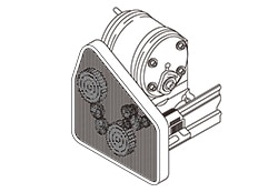
1. Requirements for fixed guards

A fixed guard shall be held in the position to which it was affixed in the following manner:
● Being permanently affixed by welding or other means; or
● Being affixed by screws and nuts so that it can only be removed or opened by the use of tools such as a special screwdriver.
 

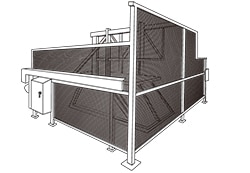
2. Requirements for movable guards

In general, movable guards shall meet the following requirements and shall associate with the control system of a machine as needed:
● Being affixed to a machine or its structure by a hinge or a guide rail not only while they are closed but also while they are open;
● Not allowing an operator to start the moving part of a machine in a case where an operator can reach it.
In addition, after starting the moving part of a machine, an operator cannot reach it. This system can be achieved with the use of an interlocking guard (with guard locking, as needed) among the movable guards; and
● Preventing the moving part of a machine from starting in a case where the guard of a movable guard is shifted from its original position or removed, or devices, including an affixed interlocking device, lack or fail. Alternatively, stop the movable part of a machine if the machine is in operation. This can be achieved through automatic monitoring of a control system.
 

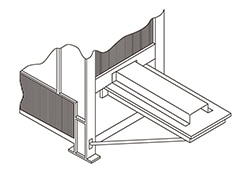
3. Requirements for interlocking guards with a start function (control guards)

An interlocking guard with a start function is a special form of interlocking guard which, once the guard is closed, automatically starts the machine without the use of a separate start controller (e.g., a start switch). This guard is allowed to implement only when all of the following requirements are satisfied:
● The guard basically satisfies all the requirements as an interlocking guard;
● The machine has a short cycle time;
●The maximum time during which the guard is open is set at a small value (e.g., equivalent to a cycle time)
Once this time has elapsed, the machine cannot be started even if the guard is closed. In this case, a reset is required;
● The machine has the size or shape that ensures that the whole body will move outside a hazard zone (to a safe position) when the guard is closed;
● The interlocking device used for the interlocking guard with a start function is designed to have, for example, a duplexed system and automatic monitoring in order to prevent an unintended start resulting from a failure; and
● The guard can reliably maintain its opened state by means such as a spring or a counterweight to prevent the guard from causing a malfunction and starting the machine while it is descending because of its own weight.
 

4. Emission reduction

For hazards that were not adequately reduced through inherently safe design measures, including noise, vibration, and hazardous substances (gas/steam), protective measures shall be taken using, for example, a noise suppressor, vibration damping equipment, or the forced ventilation of the relevant area.
 

Selection and implementation of sensitive protective equipment

Separately from guards, which are physical shields, there are regulations concerning the types and application of sensitive protective equipments. A proper selection shall be made according to the use. 

1)Selection and implementation of sensitive protective equipments

Light curtain (active opto-electronic protective device: AOPD (Note))

A equipment that performs a detection function with the photoelectric transmitter and the photodetector that detects a shade of an opaque object existing in a detection area (A type of ESPE (Note), there are Type 2 and Type 4).

Laser scanner (active opto-electronic protective device to diffuse reflection: AOPDDR (Note))

A equipment that detects an object using its photoelectric projector that emits radiation to irradiate an object existing in a predefined two-dimensional detection area and using its photodetector that detects the resulting diffusely reflected light (A type of ESPE, there is a Type 3).

Pressure detection mat
A mat that detects the presence of a human body or an object by sensing changes in pressure (e.g., changes in resistance) acting on the mat when a person steps on the mat.


Trip bar, trip wire
The sensitive protective equipments described above are used for passage detection (trip) of an opaque object like a human body, or for presence detection within a safeguarded space, or for both purposes. 


Note) Reference 
- ESPE: electro-sensitive protective equipment 
This includes light curtains, pressure detection mats, and laser scanners, and performs a protection trip or presence detection. 
- AOPD: active opto-electronic protective device
This generally refers to light curtains. A kind  of ESPE.
- AOPDDR: active opto-electronic protective device to diffuse reflection
This generally refers to laser scanners . A kind  of ESPE.

 
2) Matters to be considered in using sensitive protective equipments
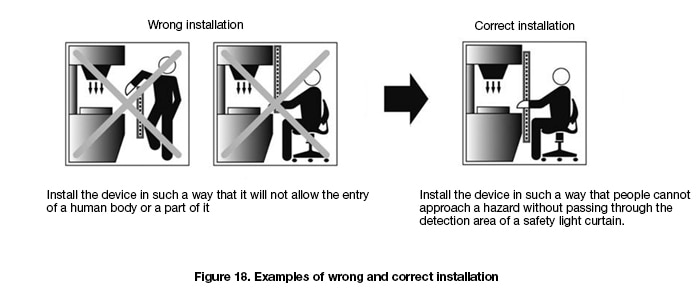
● Install a sensitive protective equipment at a proper place in such a way that people will not be able to approach a hazard by circumventing the device.
For example, when using a light curtain, install it in such a way that people will not be able to insert, for example, the hand into a hazard through a gap at the upper or the lower part / at the right or the left part by circumventing the optical axes.


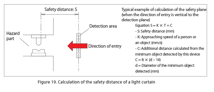
● Create a safety distance between people and a hazard by taking into account the overall stop time required for both the sensitive protective equipment and the machine.

● Sensitive protective equipments shall generate a stop command immediately they detect a person or a part of a human body.
● The exit of a person or a part of a human body from a detection area shall not, by itself, restart the hazard of a machine. In addition, a stop command by a sensitive protective equipment shall be maintained as a system until a next command is given.
● A restart shall be made possible only when an operator intentionally operates a control device (restart switch) located outside a hazard zone.
● Being able to enter into a hazard zone without being detected or being able to be present in a hazard zone shall be prevented. To achieve this, a device may be used with, for example, a fixed guard as needed.

Note that a sensitive protective equipment alone will not suffice in the cases below. Adding protective measures or reviewing the use of a sensitive protective equipment is required.
● A case where substances, such as chips of materials and cutting oil, fly out of a hazard zone
● A case where noise, dust, X rays, etc. are emitted
● A case where there is an irregular long stop time in the middle of a process, which may be misunderstood that the machine is at a complete stop, and
● A case where there is a characteristic that does not allow an emergency stop to be made in the middle of a cycle (where the moving part of a machine has a considerable inertial force).
 
3) Additional requirements for sensitive protective equipment when used for cycle initiation
There are exceptional cases where the exit of a person or a part of a human body from the detection area of a sensitive protective equipment may automatically restart a cycle of a machine primarily to improve productivity. This, however, is subject to various conditions and requirements. For details, see the text of ISO12100.
 

3-3. Typical examples of complimentary protective measures

Even after risk reduction is achieved, complimentary protective measures could have to be implemented as required by the intended use and reasonably foreseeable misuse of a machine. Complimentary protective measures have the following five typical examples:


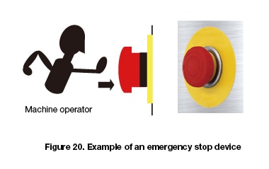
● Providing a machine with an emergency stop function so that the machine can be immediately stopped by human intention to avoid a pressing emergency situation;
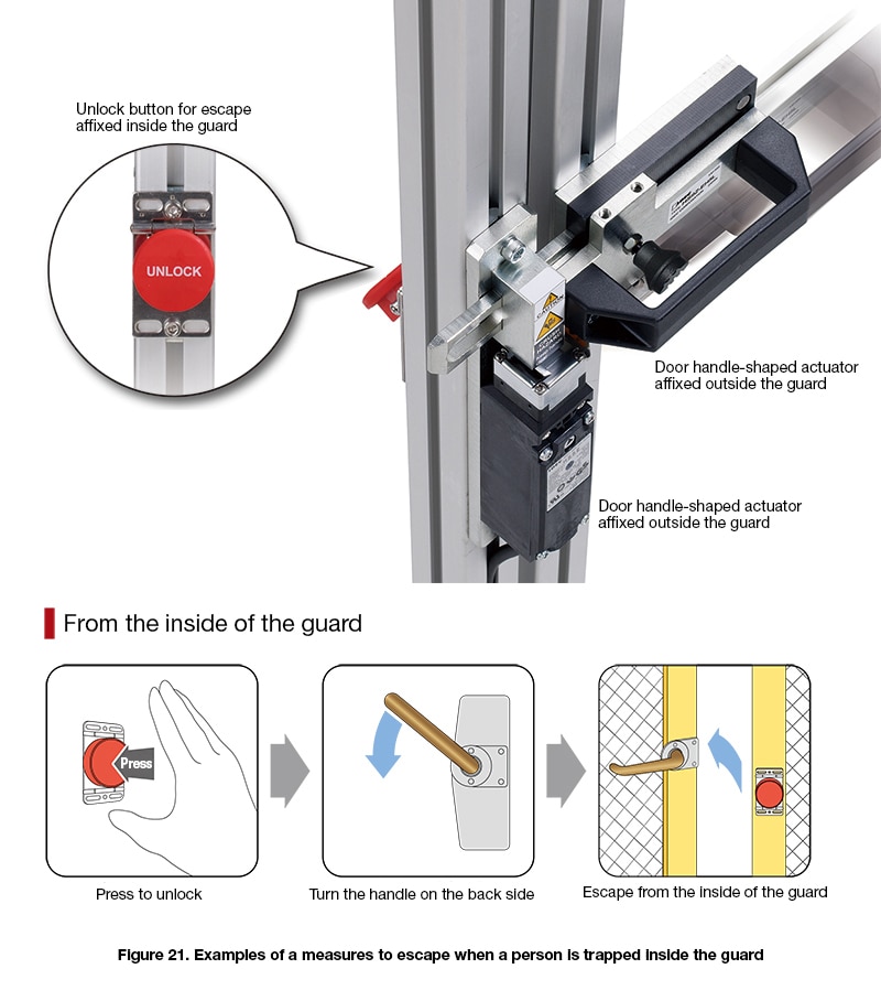
● Means of escape for a person caught in a machine, and means of rescue for cases where escape is impossible;
● Means of complete interruption of power (e.g., electric power) and means of eliminating energy that is accumulated inside, in preparation for maintenance and other occasions;
● Measures for safe handling of heavy objects including machines; and
● Measures that ensure safe approach or access to the relevant part of a machine. 

Emergency stop function

- Actuators, including an emergency stop switch (e.g., mushroom push-button), shall be clearly recognizable and quickly accessible for operation.
- When an emergency stop command is given by pressing, for example, an emergency stop switch, the machine shall be stopped as promptly as possible without creating a new hazard.
- An emergency stop command shall be maintained until it is reset (the machine maintains the stopped state).
- Resetting an emergency stop command (resetting an emergency stop switch) shall only be possible at the place where that command was given.
- Resetting an emergency stop function shall not restart the machine but shall only allow a restart.
 

Measures for the escape and rescue of trapped persons

- escape routes and shelters in installations generating operator-trapping hazards,
- arrangements for moving some elements by hand, after an emergency stop,
- arrangements for reversing the movement of some elements,
- anchorage points for descender devices,
- means of communication to enable trapped operators to call for help.
 

Measures for isolation and energy dissipation

● Being able to disconnect and separate a machine (or a relevant part) from power supply.
● Being able to lock the position of “Isolation” with a padlock or by other means in all isolating units.
● Eliminating stored energy that can cause a hazard, or if that is not possible, contain it.
 

Provisions for easy and safe handling of machines and their heavy component parts

Heavy machines shall be equipped with a device that facilitates transport by lifting gear or shall allow a device for transport to be safely attached to it.
● Being equipped with lifting tools that have slings, hooks, eyebolts, or tapped holes for appliance fixing.
● Being equipped with fork locating devices for machines to be transported by a lift truck.
 

Measures for safe access to machinery

● Machinery shall be designed so that every work can be performed on the ground level to the extent possible. In case this is not possible, provide means of a safe approach such as a platform or a staircase.
● Means of approaching an elevated spot of machinery shall provide protective measures against a falling accident (e.g., a staircase, a ladder, a safety enclosure of a ladder, mooring tools necessary to protect from a fall).
● Make walking areas with non-skid materials.
● Design/place control devices, including switches attached on a panel surface, in such a way that they will not be stepped on and used as an aid to an approach.
 

3-4. Information for use

A risk, which resides after taking inherently safe design measures as well as safeguarding and complimentary protective measures, shall be clearly communicated to users of the machine as Information for use.
Information that shall be communicated include each of the stages related to the operation of the machine, such as transport, assembly, installation, commissioning (i.e., a boot, receiving inspection, delivery, transfer), setting (e.g., a set-up), teaching or programming or a switch of a process, operation, cleaning, detection of malfunctions (faults), and maintenance, as well as disassembly, disuse, and disposal when necessary.
 
Information for use shall includes the following:
● All information necessary to safely and properly use a machine in regard to the “intended use” of the machine;
● A notice or warning about residual risks. In addition, the necessity for training and protective equipment, and if necessary, the necessity for an additional guard and a protective device shall also be included; and
● A warning, etc. about risks resulting from an unintended use or a reasonably foreseeable misuse.
 

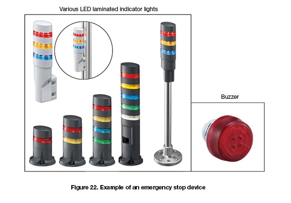
Give a warning about a hazardous event using a signal and an alarm device

An indicator light/flasher, or a buzzer/siren is used as a warning signal to indicate the condition of a machine. However, these signals need to meet the following conditions:
● They are given before a hazardous event occurs, and 
● They are signals that are clearly recognizable.

In addition, these alarm devices need to be easily inspectable (if an inspection requires a lot of time and labor, regular inspections may be neglected).
In addition, attention is required to avoid a situation in which frequent activation results in workers ignoring or deactivating them.


Display, warning message, and mark

- Name and address of the manufacturer, name of the product series, and production number (if any).
- Display of a mark of conformity with requirements (e.g., CE, UL marks).
- Various precaution / warning marks (rather than just write the word “danger,” describe what the danger is).
- It is desirable to preferentially use signs (pictographs) that can be recognized quicker than warning messages.
- Warning messages shall be written first in the language of a country in which the machine is used, and when required, in a language that an operator can understand
 

Accompanying documents (particularly, instructions handbook) 

1. Information on the transport, handling, and storage of the machine
2. Information on the installation and commissioning (i.e., a boot, receiving inspection, delivery, transfer) of the machine
3. Information relating to the machine itself  
4. Information on the use of the machine (e.g., the intended use, reasonably foreseeable misuse and prohibited matters, protective equipment to be used, and training)
5. Information on maintenance. This is, for example, presented by making a clear distinction between the following matters:
- Instructions on maintenance work that shall only be conducted by skilled personnel (i.e., maintenance personnel, specialized personnel); and
- Instructions on maintenance work that may be conducted by users (e.g., operators)
6. Information on disassembly, disuse, and disposal
7. Information on an emergency (e.g., operation methods at the time of a failure, a fire extinguisher) 
 

Instructions for use

The requirements that apply to the preparation and presentation of instructions for use include the following:
1. The font and size of printed letters shall be the most legible ones. Warnings/precautions about safety shall be emphasized using colors, symbols, and/or large block letters; and
2. Information for use shall be written first in the language of a country in which the machine is used and in the first version. When multiple languages are used, it is desirable that each language should be easily distinguishable from the other ones, and the translation and the relevant diagram should be shown together.