Erroneous positioning of an interlocking device main body or an actuator as well as positional shifts due to vibration/impact during use could have negative effects such as inability to properly detect the opening and closing of doors, and damage to the interlocking device. To address this, the requirements for the installation of interlocking devices are specified as below.
Requirements for the installation of interlocking device main bodies
In order to maintain the position of the device properly installed in accordance with manufacturer’s instructions, the following requirements need to be met:
・ To ensure reliable installation, and to require tools (Note 4) to loosen the device.
Note 4) Makeshifts, including a coin or a nail file, cannot be regarded as tools.
・ For the Type 1 interlocking devices, to have a method for fixing the position permanently after adjustment (e.g., pins, dowels).
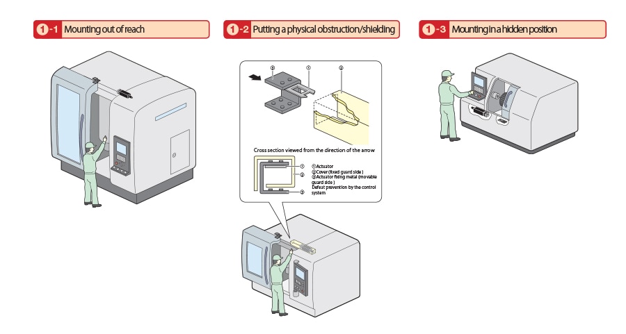
・ To have access to the interlocking device for maintenance and operation checks. However, the prevention of defeat attempted in a reasonably foreseeable manner must be considered.
・ To prevent the device from spontaneously loosening.
・ To prevent defeat of the interlocking device attempted in a reasonably foreseeable manner.
・ To be located and, if necessary, protected so that damage from foreseeable external causes is avoided.
・ To follow manufacturer’s instructions regarding the positional relationship between the actuator and the interlocking device main body.
・ Not to use the device as a mechanical stopper ( Unless the manufacturer permits).
・ Not to create a gap of the guard where a part of human body could enter inside and cause an accident, by misalignment of the installation.
・ To install the device firmly so that its correct movements can be maintained.
・ For the Type 2 interlocking devices, to have a dust protection cover or alternative means at an opening through which the actuator is inserted, or by installing the device in an orientation that can prevent dust from entering through the opening, in order to avoid the contamination and deterioration of machine parts due to dust.
Requirements for the installation of actuators
In order to minimize the possibility of a device loosening or shifting from its proper installation position during the expected life, the following requirements need to be met:
・ To ensure reliable installation, and to require tools (Note 4) to loosen fasteners of the actuators.
Note 4) An improvised implement such as a coin or a nail file cannot be considered as a tool.
・ To prevent the actuator from spontaneously loosening.
・ To be located and, if necessary, protected so that damage from foreseeable external causes is avoided.
・ Not to use the actuator as a mechanical stopper ( Unless the manufacturer permits).
・ To install the actuator firmly so that its correct movements can be maintained.
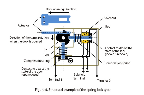
If the overall system stopping performance ≥ access time, and an interlocked guard with guard locking is required, specified conditions need to be satisfied to start a hazardous machine function. That is, both the conditions that the door is closed and locked need to be satisfied.
For example, as shown in Figure 5, the contact to detect the state of the door (open/closed) and the contact to detect the state of the lock (locked/unlocked) connected in series can satisfy these conditions.
Alternatively, realizing the NC contact, which works only while the door is closed and locked, in the structure of an interlock switch will also be able to satisfy these conditions.
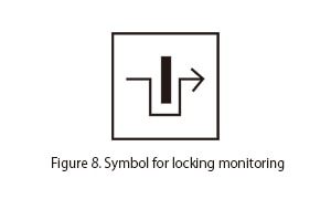
This type of circuit, which can start a hazardous machine function only while the door is closed and locked, has the locking monitoring mark shown in Figure 8.
As stipulated in ISO12100, when safety measures were taken as a result of risk assessments, it is important to confirm that they will not create a new hazard. This also applies in cases where an interlocked guard with guard locking is required for safety purposes. When the overall system stopping performance ≥ access time, and an interlocked guard with guard locking is installed to prevent people from approaching it until a hazardous machine function terminates, it is necessary to confirm that the installation has not created a new hazard. There are a variety of machines, large and small, and those requiring particular attention are large ones that have an interlocked guard with guard locking that is large enough to accommodate a whole human body. For these large machines, it is necessary to confirm that locking the interlocked guard with guard locking will not create a new hazard by trapping a worker or maintenance worker in the machine.
If such a new hazard can be created, the machine needs to be equipped with the “emergency release function” to release the guard locking from outside in case of an emergency and the “escape release function (Figure 9)” to release the guard locking from inside. In addition, to address a situation in which an interlocked guard with guard locking fails and needs to be released from outside, the “auxiliary release function (Figure 10)” may be required.