Your browser does not support JavaScript!
Skip to content Skip to navigation menu

ISO13850 | USA

ISO 13850, “Safety of machinery — Emergency stop function — Principles for design”, is a standard (type-B) that describes the safety requirements for designing emergency stop devices of machinery. Based on the risk assessment, perform risk reduction measures as necessary. The emergency stop function falls under the complementary protective measures among the protective measures.


For an explanation of the risk assessment and protective measures, check the following link.


The emergency stop function is designed to avert actual or impending emergency situations arising from the behavior of persons, or from an unexpected hazardous event, by intended human operation of the emergency stop switch. Therefore, it is necessary to prioritize the emergency stop function over all other functions and operations in all operation modes of the machine without impairing other protective functions (for example, functions to release a person trapped by the machine or extinguish fire).
In addition, it is also necessary that the machine is maintained in the stop position until the emergency stop switch is reset (described as “unlatched” in the standard) by an intended action of operators.
For this reason, it is necessary that the emergency stop function complies with the following safety requirements.
 

1 Intended actuation

1.1 Recommended actuators and nameplates

Since it is necessary that the emergency stop switch is operated by an intended action as fast as possible in an impending emergency situation, its operability/visibility should be optimized, and it should be actuated without hesitation.
For this reason, the following safety requirements are included.
 

ISO13850:2015 (JIS B9703:2019)

4.1.1.2
The emergency stop function shall be available and operational at all times.

4.3.6
The actuator of the emergency stop device shall be coloured RED. As far as a background exists behind the actuator and as far as it is practicable, the background shall be coloured YELLOW.

4.3.7
Neither the actuator nor the background should be labelled with text or symbols.
When it is necessary to identify the direction of unlatching of the actuator (button) then this identification shall have the same or nearly the same colour as the actuator.

Accordingly, it is recommended not to display text or symbols such as EMERGENCY STOP on the actuator or nameplate of an emergency stop device. In order to accommodate the diversity of languages used by machine operators, this recommendation is based on an intention to enable workers to have the following common recognition without the need to recognize texts or symbols:


A combination of a red actuator and yellow background = Emergency stop device (even if there are no texts/symbols)

For example, when a person intends to actuate an emergency stop switch, the operator may momentarily hesitate in the actuation if the switch displays texts/symbols that the person cannot read/understand, delaying the actuation of the emergency stop device. Even if the displayed texts can be read/understood, it is also expected that actuation following the recognition of only the color combination of red and yellow is faster than actuation following the recognition of texts/symbols.


For this reason, use one of the blank nameplates shown below when using a nameplate for an emergency stop switch.
 
IDEC Emergency Stop Switch Nameplates
Hole SizeDescriptionLegendPart No.MaterialPlate Color
Ø16For Ø30 Operator(blank)HAAV-0PolyamideYellow
For Ø40 OperatorHAAV4-0
Ø22For Ø40 OperatorHWAV-0-YPolyamide
For Ø60 OperatorHWAV5-0PBT
Ø30HNAV-0Polyamide

Furthermore, in order to prevent operators from hesitating in the actuation of an emergency stop switch, it is required that arrows showing the direction of unlatching the emergency stop switch should not be too conspicuous. The reason is that some workers may mistakenly think that such arrows indicate the direction of actuating the emergency stop switch.

For the emergency stop switches, use the following compliant products.

1.2 Location of emergency stop devices

Since emergency stop switches are mainly used in an emergency situation, there are safety requirements concerning their locations to ensure that they can be actuated as fast as possible.
 
ISO13850:2015(JIS B9703:2019)
4.3.2
An emergency stop device shall be located:
— at each operator control station, except where the risk assessment indicates that this is not necessary;
— at other locations, as determined by the risk assessment

For example:
— at entrance and exit locations;
— at locations where intervention to the machinery is needed, e.g. operations with a hold-to-run control function;
— at all places where a man / machine interaction is expected by design (loading / unloading zone for example).

Emergency stop devices shall be positioned so that they are directly accessible and capable of nonhazardous actuation by the operator and others who could need to actuate them.
The actuator of emergency stop device intended to be actuated by hand should be mounted between 0.6 m and 1.7 m above the access level (e.g. floor level, platform level).

For new and/or existing machines, confirm that emergency stop switches are located at locations which satisfy the above safety requirements. Confirm that emergency stop switches are located near the work locations and can be actuated not only during stationary time, such as automatic operations, but also during non-stationary work, such as machine setup and maintenance.


2 Prevention of unintended actuation

Until the revisions of the ISO standards in 2015 and the JIS standards in 2019, the use of a switch guard (used synonymously with protective shroud) with an emergency stop switch has not been permitted for machinery subject to the standards such as machine tools and food machinery.
However, these revisions have allowed the use of a switch guard (protective shroud) under certain conditions, because the “Prevention of unintended actuation of emergency stop devices” is added as a safety requirement.
ISO13850:2015(JIS B9703:2019)
3.7
protective shroud
Mechanical measure provided to reduce the possibility of unintended actuation of an emergency stop device..

4.5
Prevention of unintended actuation of an emergency stop device
The emergency stop device shall be designed to avoid unintended actuation.
So far as practicable, unintended actuation shall be prevented by location rather than the use of other application design measures.
The actuation of the emergency stop device shall not be impaired.
To prevent unintended actuation of the emergency stop device some precautions can be taken, e.g.:
— locate the emergency stop device away from foreseeable heavily trafficked areas
— select the type of emergency stop device
— select appropriate size or shape of the emergency stop device

The use of a protective shroud around the emergency stop device should be avoided, except when necessary to prevent unintended actuation and other measures are not practicable.
A protective shroud shall not have any sharp corners or edges or rough surfaces which could lead to injury. Corners and edges shall be de-burred and surfaces shall be smooth to the touch.

If it is determined that a switch guard (protective shroud) is necessary after considering the location of the emergency stop switches in Section 4.3.2 and the prevention measures against unintended actuation in Section 4.5, use one from the following combinations of the switch guards and the emergency stop switches.
The following combinations have been confirmed by TÜV Rheinland for complying with the requirements of emergency stop switches with a protective shroud, specified by ISO 13850:2015.

3 Intended resetting

3.1 Importance of human intention in resetting

Since an emergency stop switch is primarily used by an intended action during an emergency situation, the importance of an intended action in its resetting the emergency stop switch is also described in the safety requirements.

ISO13850:2015(JIS B9703:2019)

4.1.1.2
The emergency stop function shall be reset by intentional human action. Resetting of the emergency stop function shall be operated by disengagement of an emergency stop device.

3.2 Description concerning reset in the instruction manual

Since an emergency stop switch is primarily used in an emergency situation, information concerning machine reset is described in the safety requirements.
 

ISO13850:2015(JIS B9703:2019)

4.1.4 Disengagement (e.g. unlatching) of the emergency stop device
The instructions for use of the machine shall state that, after actuation and before disengaging the device(s), the machinery shall be inspected in order to detect the reason for actuation.

The actuation of an emergency stop switch means that there is a possibility that an emergency situation has occurred. Therefore, before resetting the emergency stop switch, it is necessary to check the cause of the actuation and confirm that safety is ensured. Since it is necessary to disseminate this information to users, the instruction manual must describe the inspections required after actuating and before resetting emergency stop switches.
 

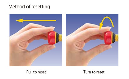
3.3 Unrecommended reset type

The use of some emergency stop devices is no longer recommended after the revision. Although their use is not prohibited, the following conditions must be satisfied to use those devices.
 

ISO13850:2015(JIS B9703:2019)

4.3.6
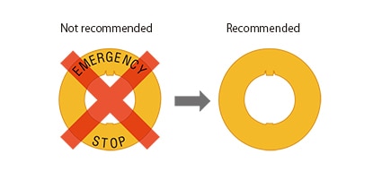
Emergency stop device requiring a key on the actuator to be disengaged (unlatched) should be avoided.
When an emergency stop actuator can only be disengaged by using a key, to avoid injuries to hands;
— Instruction for use of the machine shall describe the correct use of the key.
— Provide a warning that the key should only be in the actuator of the device to disengage the actuator.

These safety requirements were added because of the following. A key to reset the emergency stop switch may be left inserted into an actuator. If a person unaware of the situation operates the emergency stop switch without thinking carefully in an emergency, the person can injure his/her hand with the key inserted into the actuator. Therefore, the use of the key reset type emergency stop switch is no longer recommended.
In addition, when using a key reset type emergency stop switch after performing the risk assessment, implement measures based on the above safety requirements.
 

4 Prevention of unintended reset

As described above, human intention plays an important role in the emergency stop function. Intended actuations, prevention of unintended actuations, and intended reset operations are specified in the standards. Note that prevention of unintended reset operations is not specified as a safety requirement.

However, “Prevention of unintended reset operation” and the “Intended reset operation” are both important as a practical matter. The prevention of an unintended reset operation requires special attention if multiple persons enter a danger zone, for example, during machine setup or maintenance. In order to prevent an unintended reset, the key reset type emergency stop switches, shown in Section 3.3, have conventionally been used. As mentioned above, this is no longer recommended. Therefore, another measure to prevent an unintended reset is necessary.

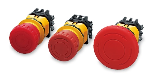
The use of a padlock to protect the emergency stop switch is one such alternative measure. As shown in the figure below, only after actuating the emergency stop switch, each worker can padlock the switch with his/her own padlock. By keeping the key to himself/herself, an unauthorized reset by other workers can be prevented. Since the machine will not be restarted, each worker can ensure his/her own safety.

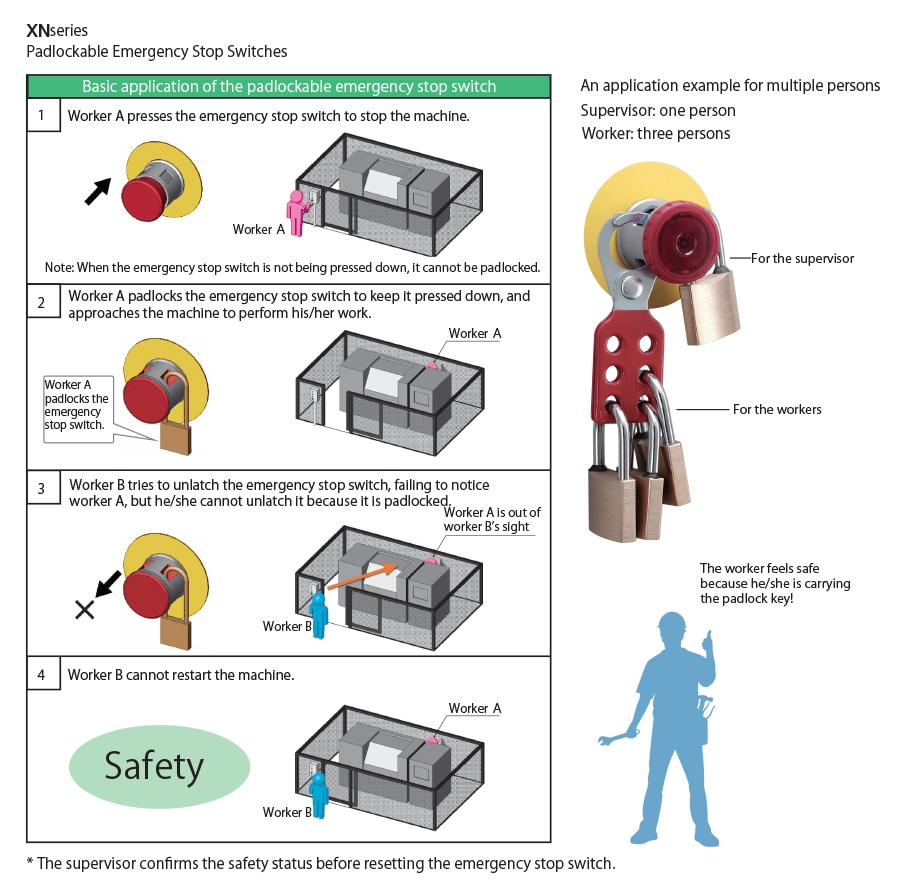
According to your applications, use the following padlockable emergency stop switches.

5 Span of control of emergency stop device(s)

In principle, when actuating an emergency stop device, the entire machine system should be stopped. However, stopping a complicated machine or machine system entirely could create additional hazards or unnecessarily affect production. In such a case, it is possible as an exception to set the “Span of control” to partially stop the machine or machine system as shown below.
 

ISO13850:2015(JIS B9703:2019)

4.1.2
The span of control of each emergency stop device shall cover the whole machine. As an exception, a single span of control may not be appropriate when, for example, stopping all linked machinery could create additional hazards or unnecessarily affect production. Each span of control can cover section(s) of a machine, an entire machine or a group of machines.

4.1.2.1
More than one span of control can be applied, if the following requirements are met:
— the spans of control shall be clearly defined and identifiable;
— emergency stop devices shall be readily associated with the hazard requiring an emergency stop;
— the span of control of an emergency stop device shall be identifiable at the operating position of each emergency stop device
— actuation of an emergency stop device shall not create additional hazard(s) or increase the risk(s), in any span of control;
— actuation of an emergency stop device in one span of control shall not prevent the initiation of an emergency stop function in
another span of control;
— information for use of the machine shall include information on the span of control of emergency stop device.


Examples demonstrating the concept of span of control
Key:
1: emergency stop device
2: span of control
3: section of machine or machine


This safety requirement allows precise setting of the span of the machine that is stopped by an emergency stop device according to the actual situation.
Implement measures based on the above safety requirement before setting the span of control.


6 Required performance level (PLr), safety integrity level (SIL)

The minimum required performance level (PLr) and safety integrity level (SIL) required for the emergency stop function are specified as follows.
 

ISO13850:2015(JIS B9703:2019)

4.1.5
Emergency stop equipment

 
4.1.5.1
The safety related parts of the control system or subsystems which perform the emergency stop function shall comply with the relevant
requirements of ISO 13849-1 and/or IEC 62061.
Determination of the Performance Level (PL) or SIL required should take into account the purpose of the emergency stop function, but the minimum required is PLr c or SIL 1.


Depending on the result of the risk assessment and the safety requirements of the type-C standards for the subject machinery, a minimum of PLr = c or SIL 1 is required for the emergency stop function.

For an explanation of PLr and SIL, check the following link.


Also, in the support software SISTEMA for the safety evaluation according to ISO 13849-1 and/or IEC 62061, the following emergency stop switches are registered.

When considering PL and SIL, use SISTEMA as necessary. For an explanation of SISTEMA, check the following link.


7 Emergency stop function on portable operator control stations

Following advancements in technology, user demand has risen, such as the use of the cable detachable type so that one teaching pendant can be used with multiple robots or improvement in convenience by eliminating the wiring.
However, since safety aspects must be considered carefully, the contents for detachable and wireless operator control stations have been updated in this revision as follows.
 

ISO13850:2015(JIS B9703:2019)


4.3.8
When emergency stop devices are installed on detachable or cableless operator control stations (e.g. pluggable portable teaching pendants), at least one emergency stop device shall be permanently available (e.g. in a fixed position) on the machine.
In addition, at least one of the following measures shall be applied to avoid confusion between active and inactive emergency stop devices:
— device colour changing through illumination of the active emergency stop device;
— automatic (self-actuating) covering of inactive emergency stop devices; where this is not practicable, manually-applied covering may be used, provided that the cover remains attached to the operator control stations;
— provision of proper storage for detached or cableless operator control stations.

The instructions for use of the machine shall state, which measure has been applied in order to avoid confusion between active or inactive emergency stop device(s). The correct operation of this measure shall be explained.

The above safety requirement aims to prevent accidents when mistakenly operating the inactive emergency stop devices on the detachable teaching pendants or cableless operator control stations. Implement measures based on the above safety requirement when choosing a detachable teaching pendant or cableless operator control station.